
Juniper JN0-281 Practice Exams
Last updated on Oct 21,2026- Exam Code: JN0-281
- Exam Name: Data Center, Associate (JNCIA-DC)
- Certification Provider: Juniper
- Latest update: Oct 21,2026
Which three actions are required to implement filter-based forwarding? (Choose three.)
- A . You must create an instance-type forwarding routing instance.
- B . You must create an instance-type vrf routing instance.
- C . You must create a match filter.
- D . You must create a security policy.
- E . You must create a RIB group.
A, C, E
Explanation:
Filter-Based Forwarding (FBF) in Junos OS allows traffic to be routed based on specific criteria such as source address, rather than just the destination address. This is useful in scenarios like policy routing or providing multiple paths for different types of traffic.
Step-by-Step Breakdown:
Instance-Type Forwarding:
You must create an instance-type forwarding routing instance. This routing instance allows for different routing tables based on the incoming packet filter.
Command:
set routing-instances FBF-instance instance-type forwarding
Match Filter:
You need to create a filter to match the traffic that will be forwarded according to your custom routing policy. This filter is applied to an interface to determine which traffic will use the custom forwarding instance.
Command Example:
set firewall family inet filter FBF-filter term 1 from source-address <address> set firewall family inet filter FBF-filter term 1 then routing-instance FBF-instance RIB Group:
A RIB (Routing Information Base) group is necessary to share routes between the primary routing table and the custom routing instance. This allows FBF traffic to use the routing information from other routing tables.
Command Example:
set routing-options rib-groups FBF-group import-rib inet.0
set routing-instances FBF-instance routing-options rib-group FBF-group
Juniper
Reference: FBF Configuration: Filter-based forwarding requires these specific steps to redirect traffic to a custom routing table based on filter criteria.
What are two consequences of having all network devices in a single collision domain? (Choose two.)
- A . The amount of network resource consumption does not change.
- B . The chance of packet collision is decreased.
- C . The chance of packet collision is increased.
- D . The amount of network resource consumption is increased.
C, D
Explanation:
A collision domain is a network segment where data packets can "collide" with one another when being sent on the same network medium.
Step-by-Step Breakdown:
Increased Collision Probability:
If all devices are in a single collision domain, the likelihood of packet collisions increases as more devices attempt to send packets simultaneously, leading to network inefficiencies. Increased Resource Consumption:
More collisions result in increased network resource consumption as devices need to retransmit packets, causing higher utilization of bandwidth and slowing down network performance. Juniper
Reference: Collision Domains: Proper network segmentation using switches reduces collision domains, thereby improving network performance and reducing packet collisions.
Exhibit:
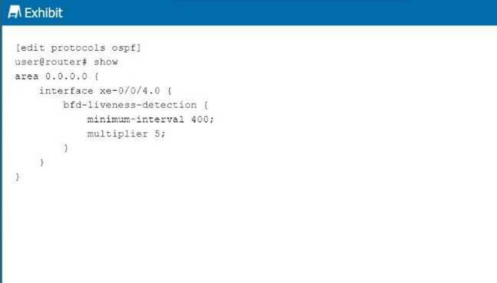
Referring to the exhibit, at which interval will the interface be considered down if no hello packets are received?
- A . 2000 seconds
- B . 400 milliseconds
- C . 400 seconds
- D . 2000 milliseconds
D
Explanation:
The exhibit shows the configuration of Bidirectional Forwarding Detection (BFD) for OSPF on interface xe-0/0/4.0, with the following parameters: minimum-interval: 400 milliseconds
multiplier: 5
Step-by-Step Breakdown:
BFD Liveness Detection:
BFD is used to detect link failures at sub-second intervals, providing faster convergence times for routing protocols like OSPF. The minimum-interval is the time between BFD control packets (in milliseconds), and the multiplier indicates how many missed BFD packets trigger a failure.
Calculating Failure Detection Time:
The failure detection interval is calculated as:
Failure Interval=minimum-interval×multipliertext{Failure Interval} = text{minimum-interval} times text{multiplier}Failure Interval=minimum-interval×multiplier In this case:
400 milliseconds×5=2000 milliseconds(2seconds)400 , text{milliseconds} times 5 = 2000 , text{milliseconds} (2 seconds)400milliseconds×5=2000milliseconds(2seconds) Conclusion:
If no BFD control packets are received within 2000 milliseconds (2 seconds), the interface will be considered down, triggering OSPF to recalculate routes. Juniper
Reference: BFD Configuration: BFD parameters such as minimum-interval and multiplier are used to fine-tune the failure detection time for faster convergence.
What is the primary purpose of an IRB Layer 3 interface?
- A . to provide load balancing
- B . to provide a default VLAN ID
- C . to provide inter-VLAN routing
- D . to provide port security
C
Explanation:
The primary purpose of an IRB (Integrated Routing and Bridging) interface is to enable inter-VLAN routing in a Layer 3 environment. An IRB interface in Junos combines the functionality of both Layer 2 bridging (switching) and Layer 3 routing, allowing devices in different VLANs to communicate with each other.
Step-by-Step Breakdown:
VLANs and Layer 2 Switching:
Devices within the same VLAN can communicate directly through Layer 2 switching. However, communication between devices in different VLANs requires Layer 3 routing.
IRB Interface for Inter-VLAN Routing:
The IRB interface provides a Layer 3 gateway for each VLAN, enabling routing between VLANs. Without an IRB interface, devices in different VLANs would not be able to communicate.
Configuration:
In Juniper devices, the IRB interface is configured by assigning Layer 3 IP addresses to it. These IP addresses serve as the default gateway for devices in different VLANs.
Example configuration:
set interfaces irb unit 0 family inet address 192.168.1.1/24 set vlans vlan-10 l3-interface irb.0
This allows VLAN 10 to use the IRB interface for routing.
Juniper
Reference: IRB Use Case: Inter-VLAN routing is essential in data centers where multiple VLANs are deployed, and Juniper’s EX and QFX series switches support IRB configurations for this purpose.
You are configuring an aggregate route. In this scenario, which two statements are correct? (Choose two.)
- A . Reject will silently drop the traffic.
- B . Discard will silently drop the traffic.
- C . Reject will send an ICMP Destination Unreachable message back to the sender.
- D . Discard will send an ICMP Destination Unreachable message back to the sender.
B, C
Explanation:
When configuring an aggregate route, you have options for how to handle traffic that matches the route but does not match any more specific route in the routing table.
Two actions can be taken:
discard and reject.
Step-by-Step Breakdown:
Discard:
The discard option will silently drop packets that match the aggregate route. No notification is sent to the sender, and the packet is simply dropped.
Reject:
The reject option will drop the packet and also send an ICMP Destination Unreachable message back to the sender. This informs the sender that the packet could not be delivered because there is no specific route available.
Juniper
Reference: Aggregate Routes: The reject and discard next-hop options provide different levels of feedback when packets cannot be routed, and they can be used to control how unreachable destinations are handled.
You are troubleshooting a downed BGP session.
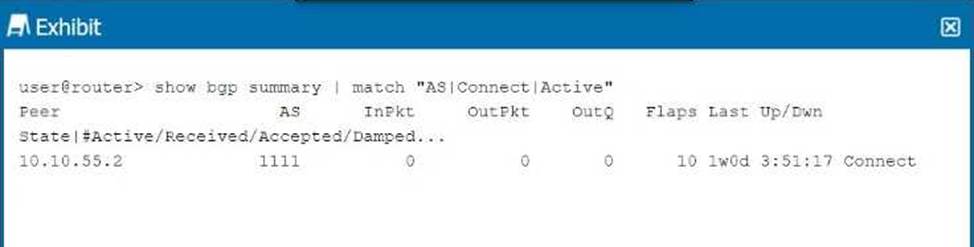
Referring to the exhibit, what is the cause of the problem?
- A . The UDP session between the peers has not been established.
- B . The local peer has sent an Open message but not received one from the remote peer.
- C . The TCP session between the peers has not been established.
- D . The local peer has sent an Update message but not received one from the remote peer.
C
Explanation:
The BGP session in the exhibit shows the state as Connect, which indicates that the TCP session between the BGP peers has not been fully established.
Step-by-Step Breakdown:
BGP State "Connect":
The Connect state is the second stage in the BGP finite state machine (FSM). At this stage, BGP is trying to establish a TCP session with the peer, but the session has not yet been successfully established.
A successful TCP three-way handshake (SYN, SYN-ACK, ACK) is required before BGP can progress to the OpenSent state, where the peers exchange BGP Open messages.
Possible Causes:
A firewall blocking TCP port 179.
Incorrect IP addresses or network connectivity issues between the BGP peers. Juniper
Reference: BGP Troubleshooting: In Junos, if a BGP session is stuck in the Connect state, the issue is likely due to a failure in establishing the underlying TCP connection.
You are creating an IP fabric underlay and want to use OSPF as your routing protocol.
In this scenario, which statement is correct?
- A . All leaf devices must be configured in separate OSPF areas.
- B . All leaf and spine devices must be the same model to ensure the proper load-balancing behavior.
- C . Interface speeds should be the same throughout the fabric to ensure that all links are utilized.
- D . All spine devices must use the same router ID.
C
Explanation:
When creating an IP fabric underlay using OSPF as the routing protocol, consistent interface speeds are important to ensure optimal traffic distribution and utilization of all links.
Step-by-Step Breakdown:
OSPF and Interface Speeds:
OSPF calculates the cost of a link based on its bandwidth.
The default cost calculation in OSPF is:

If interface speeds vary significantly, OSPF may choose paths with lower cost (higher bandwidth), resulting in some links being underutilized.
Equal Utilization:
To ensure that all links are equally utilized in an IP fabric, it is recommended to maintain uniform interface speeds across the fabric. This ensures balanced load sharing across all available paths. Juniper
Reference: IP Fabric with OSPF: Juniper recommends consistent interface speeds to maintain even traffic distribution and optimal link utilization in IP fabric underlay designs.
A generated route is configured under which hierarchy?
- A . [edit policy-options]
- B . [edit routing-instance]
- C . [edit routing-options]
- D . [edit protocols]
C
Explanation:
A generated route in Junos OS is configured under the [edit routing-options] hierarchy.
Step-by-Step Breakdown:
Generated Routes:
A generated route is created based on the presence of more specific routes in the routing table. It acts as a summary route and is generated when any of its contributing routes are active. This is commonly used to create aggregate routes in OSPF, BGP, or other protocols. Configuration Hierarchy:
The configuration for generated routes is placed under [edit routing-options], where other static and
routing policies are also defined.
Command Example:
set routing-options generate route 10.10.0.0/16
Juniper
Reference: Routing Options: Juniper routers use the routing-options hierarchy to configure generated routes and other static routing behaviors.
Exhibit:
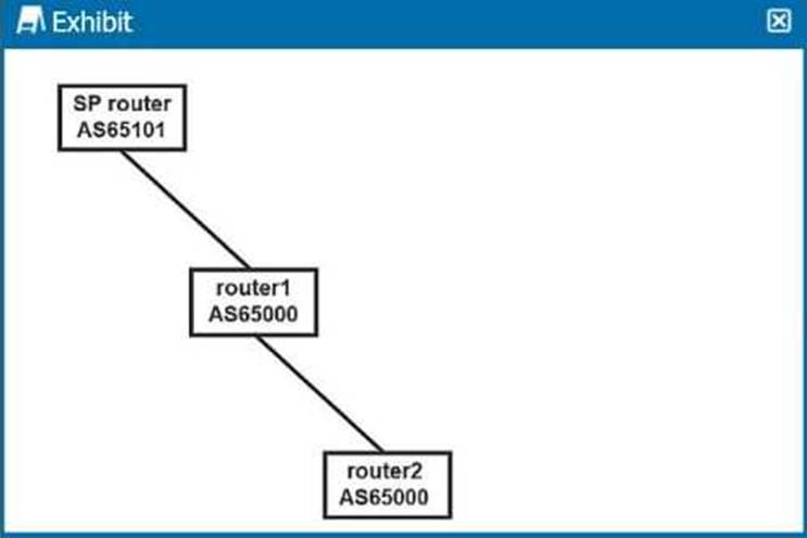
Referring to the exhibit, which two statements are correct about default BGP advertisements? (Choose two.)
- A . When routes advertised by router2 are received by the SP router, they will contain the next-hop address of router2.
- B . When routes advertised by router2 are received by the SP router, they will contain the next-hop
address of router1. - C . When routes advertised by the SP router are received by router2, they will contain the next-hop address of the SP router.
- D . When routes advertised by the SP router are received by router2, they will contain the next-hop address of router1.
B, D
Explanation:
The exhibit shows a BGP peering scenario between three routers: router1 and router2 are part of the same AS (AS65000), while the SP router is in a different AS (AS65101). This indicates an EBGP (External BGP) peering between the SP router and router1, and IBGP between router1 and router2.
Step-by-Step Breakdown:
Next-Hop Behavior in BGP:
IBGP: In IBGP, the next-hop address is not modified when advertising routes within the same AS. Thus, when router1 advertises routes learned from router2 to the SP router, it will keep the next-hop address of router1, not router2.
EBGP: In EBGP, the next-hop address is modified. When router1 receives routes from the SP router, it will advertise them to router2 with the next-hop address of router1. Route Propagation:
Routes received by router1 from router2 will be advertised to the SP router with router1 as the next hop.
Similarly, routes advertised by the SP router will be passed on to router2, with router1 remaining as
the next hop.
Juniper
Reference: BGP Next-Hop: Juniper’s BGP implementations follow standard BGP next-hop behavior, where the next-hop is modified in EBGP but not in IBGP, ensuring proper route advertisement across autonomous systems.
What is the behavior of the default export policy for OSPF?
- A . Accept all routes.
- B . Reject all routes.
- C . Redistribute all routes.
- D . Forward all routes.
B
Explanation:
In Junos, the default export policy for OSPF is to reject all routes from being exported.
Step-by-Step Breakdown:
Default Export Policy:
By default, OSPF in Junos does not export any routes to other routing protocols or neighbors. This is a safety mechanism to prevent unintended route advertisements. Custom Export Policies:
If you need to export routes, you must create a custom export policy that explicitly defines which routes to advertise.
Example: You can create an export policy to redistribute static or connected routes into OSPF.
Juniper
Reference: OSPF Export Behavior: In Juniper devices, the default policy for OSPF is to reject route advertisements unless explicitly configured otherwise through custom policies.