
Juniper JN0-281 Practice Exams
Last updated on Oct 21,2026- Exam Code: JN0-281
- Exam Name: Data Center, Associate (JNCIA-DC)
- Certification Provider: Juniper
- Latest update: Oct 21,2026
Question #21
Which two statements describe an IP fabric? (Choose two.)
- A . An IP fabric allows devices to always be one hop away.
- B . An IP fabric depends on Layer 2 switching.
- C . An IP fabric uses spine and leaf devices.
- D . An IP fabric provides traffic load sharing.
Correct Answer: C, D
C, D
Explanation:
An IP fabric is a network topology designed to provide a scalable, low-latency architecture that is
typically implemented in modern data centers. It uses spine and leaf switches and enables efficient
traffic load sharing across the network.
Step-by-Step Breakdown:
Spine-Leaf Architecture:
Leaf Devices: These switches connect to servers and edge devices within the data center. Each leaf switch connects to every spine switch.
Spine Devices: These high-performance switches interconnect all the leaf switches. There are no direct connections between leaf switches or spine switches. This architecture ensures that any two endpoints within the fabric are only one hop away from each other, minimizing latency.
Traffic Load Sharing:
An IP fabric leverages Equal-Cost Multipath (ECMP) to distribute traffic evenly across all available paths between leaf and spine switches, providing effective load balancing. This ensures that no single link becomes a bottleneck and that traffic is distributed efficiently across the network. Juniper
Reference: Juniper provides QFX Series switches optimized for IP fabric topologies, allowing for scalable deployments in modern data centers.
EVPN-VXLAN: Often used in IP fabrics to extend Layer 2 services across the fabric with Layer 3 underlay, enabling both efficient routing and bridging.
Question #22
Which two statements are correct about aggregate routes and generated routes? (Choose two.)
- A . An aggregate route does not have a forwarding next hop.
- B . An aggregate route has a forwarding next hop.
- C . A generated route has a forwarding next hop.
- D . A generated route does not have a forwarding next hop.
Correct Answer: A, C
A, C
Explanation:
Aggregate routes and generated routes are used to create summarized routes in Junos, but they behave differently in terms of forwarding.
Step-by-Step Breakdown:
Aggregate Routes:
An aggregate route summarizes a set of more specific routes, but it does not have a direct forwarding next hop. Instead, it points to the more specific routes for actual packet forwarding.
Generated Routes:
A generated route also summarizes specific routes, but it has a forwarding next hop that is determined based on the availability of contributing routes. The generated route can be used to directly forward traffic.
Juniper
Reference: Aggregate and Generated Routes: In Junos, aggregate routes rely on more specific routes for forwarding, while generated routes can forward traffic directly based on their next-hop information.
Question #23
A switch receives a frame with a MAC address of FF-FF-FF-FF-FF-FF.
Which action will the switch take on this frame?
- A . It will flood it out of all interfaces, except for the ingress interface.
- B . It will flood it out of all interfaces, except for the directly connected VLAN.
- C . It will flood it out of all interfaces, except for the next-hop interface.
- D . It will flood it out of all interfaces.
Correct Answer: A
A
Explanation:
A MAC address of FF-FF-FF-FF-FF-FF is the Ethernet broadcast address. When a switch receives a frame with this destination MAC address, it is required to forward the frame to all interfaces except the one it was received on.
Step-by-Step Breakdown: Broadcast Frame Handling:
When a frame with the broadcast MAC address is received, the switch will flood it out of all active ports that belong to the same VLAN as the incoming frame. The broadcast frame is not sent back out of the ingress interface (the interface where the frame was originally received).
Purpose of Flooding:
Broadcasting is used to ensure that the frame reaches all devices within the broadcast domain (all devices within the same VLAN), which may not have a specific entry for the MAC address in their MAC address table.
Juniper
Reference: Layer 2 Frame Forwarding: Juniper switches flood broadcast frames to all ports in the same VLAN, except the port the frame was received on.
Question #24
Which statement about switches is correct?
- A . Each port is a member of VLAN 2 by default.
- B . Every port is in a unique collision domain.
- C . Each port is in a unique broadcast domain by default.
- D . All ports reside in the same collision domain.
Correct Answer: B
B
Explanation:
Each port on a modern switch creates a separate collision domain. This allows multiple devices to communicate simultaneously without collisions on different ports.
Step-by-Step Breakdown:
Collision Domain:
A collision domain is a network segment where data packets can collide if two devices send packets simultaneously.
On a switch, each port creates a separate collision domain, so collisions only occur if two devices connected to the same port (through a hub, for instance) try to send data at the same time. Switches vs Hubs:
Unlike hubs, which have one large collision domain, switches isolate collisions to individual ports,
improving performance.
Juniper
Reference: Switch Port Behavior: In Juniper switches, each port operates in its own collision domain, enhancing network efficiency by reducing the chances of packet collisions.
Question #25
What is the definition of a trunk interface on a switch?
- A . An interface that carries multiple VLANs.
- B . An interface that carries high bandwidth.
- C . An interface that connects directly to powerful servers.
- D . An interface that carries excess traffic.
Correct Answer: A
A
Explanation:
A trunk interface on a switch is used to carry traffic for multiple VLANs between switches or between a switch and another network device, like a router. Trunk interfaces use 802.1Q tagging to identify which VLAN the traffic belongs to.
Step-by-Step Breakdown:
Trunk Ports:
Trunk ports are typically used for inter-switch links or switch-to-router links where multiple VLANs need to be carried over the same physical connection.
VLAN traffic is tagged with a VLAN ID to ensure that it is properly identified as it crosses the trunk link.
Question #26
Which state in the adjacency process do OSPF routers check the MTU size?
- A . Init
- B . Exchange
- C . Done
- D . ExStart
Correct Answer: B
B
Explanation:
In OSPF, routers exchange link-state information in different stages to establish full adjacency.
The MTU size is checked during the Exchange state.
Step-by-Step Breakdown:
OSPF Adjacency Process:
OSPF routers go through multiple stages when forming an adjacency: Down, Init, 2-Way, ExStart,
Exchange, Loading, and Full.
Exchange State:
During the Exchange state, OSPF routers exchange Database Description (DBD) packets to describe their link-state databases. The MTU size is checked at this stage to ensure both routers can successfully exchange these packets without fragmentation.
If there is an MTU mismatch, the routers may fail to proceed past the Exchange state.
Juniper
Reference: MTU Checking in OSPF: Junos uses the Exchange state to check for MTU mismatches, ensuring that routers can properly exchange database information without packet fragmentation issues.
Question #27
Which two statements are correct about rules for EBGP and IBGP? (Choose two.)
- A . EBGP peers have a TTL of 1, while IBGP peers have a TTL of 255.
- B . EBGP peers have a TTL of 255, while IBGP peers have a TTL of 1.
- C . EBGP routes are more preferred than IBGP routes.
- D . IBGP routes are more preferred than EBGP routes.
Correct Answer: A, C
A, C
Explanation:
EBGP (External BGP) and IBGP (Internal BGP) operate with different rules due to the nature of their
relationships.
Step-by-Step Breakdown:
TTL Differences:
EBGP: By default, EBGP peers have a TTL of 1, meaning they must be directly connected, or the TTL needs to be manually increased for multihop EBGP.
IBGP: IBGP peers within the same AS have a TTL of 255, as they are expected to communicate over multiple hops within the AS.
Preference for EBGP Routes:
Routes learned via EBGP are typically preferred over IBGP routes. This is because EBGP routes are considered more reliable since they originate outside the AS, while IBGP routes are internal. Juniper
Reference: BGP Configuration: The different handling of TTL and route preferences between EBGP and IBGP ensures proper route selection and security within Junos-based networks.
Question #28
Exhibit:
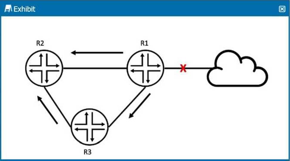
R2 received an OSPF update from R1, and it received the same update from R3.
Referring to the exhibit, what will R2 do?
- A . R2 ignores the update from R1.
- B . R2 does nothing with R3’s update.
- C . R2 ignores the update from R3.
- D . R2 acknowledges R3 and discards it.
Correct Answer: C
C
Explanation:
In the exhibit, R2 receives the same OSPF update from both R1 and R3. OSPF has mechanisms to prevent unnecessary processing of duplicate LSAs (Link-State Advertisements).
Step-by-Step Breakdown:
OSPF LSA Processing:
OSPF uses LSAs to exchange link-state information between routers. When a router receives an LSA, it checks if it already has a copy of the LSA in its Link-State Database (LSDB).
Duplicate LSAs:
If R2 has already received and processed the update from R1, it will ignore the update from R3 because it already has the same LSA in its database. OSPF uses the concept of flooding, but it does not reprocess LSAs that it already knows about.
R2 Behavior:
R2 will keep the update from R1 (the first one it received) and will ignore the same LSA from R3, as it
is already in the LSDB.
Juniper
Reference: OSPF LSA Processing: Junos adheres to OSPF standards, ensuring that duplicate LSAs are not processed multiple times to avoid unnecessary recalculations.
Question #29
Which statement is correct about a three-stage IP fabric underlay?
- A . Every ingress interface into the fabric is only two hops away from the egress interface.
- B . Every spine device can communicate directly with other spine devices.
- C . Every leaf device can communicate directly with other leaf devices.
- D . Every server that connects to a three-stage IP fabric must be multihomed.
Correct Answer: A
A
Explanation:
In a three-stage IP fabric (also known as a Clos fabric), traffic between any two points (ingress to egress) in the fabric is only two hops away.
Step-by-Step Breakdown:
Three-Stage IP Fabric:
Leaf Layer: Leaf switches connect directly to servers and edge devices.
Spine Layer: Spine switches provide connectivity between leaf switches but do not connect to each
other directly.
Two-Hop Communication:
In this architecture, every leaf switch is connected to every spine switch. Therefore, when a packet enters the fabric via an ingress leaf switch, it is forwarded to a spine switch, which then directs the packet to the correct egress leaf switch. This path always involves exactly two hops: Ingress leaf → Spine → Egress leaf.
Benefits:
This consistent two-hop path ensures predictable latency and makes the network highly scalable
while maintaining low complexity.
Juniper
Reference: IP Fabric Architecture: This two-hop property of Clos fabrics is a hallmark of spine-leaf designs, as supported by Juniper’s QFX and EX switches in data centers.
Question #30
Which signaling protocol is used for EVPN?
- A . OSPF
- B . PIM
- C . IS-IS
- D . BGP
Correct Answer: D
D
Explanation:
EVPN (Ethernet Virtual Private Network) is a standard protocol used for building Layer 2 and Layer 3
VPNs over an IP or MPLS network. The signaling protocol used for EVPN is BGP (Border Gateway Protocol).
Step-by-Step Breakdown:
BGP as the EVPN Signaling Protocol:
EVPN uses BGP to exchange MAC address reachability information between routers (PE devices). This enables devices to learn which MAC addresses are reachable through which PE devices, facilitating Layer 2 forwarding across an IP or MPLS core.
BGP Extensions for EVPN:
BGP is extended with new address families (e.g., EVPN NLRI) to carry both MAC and IP address information, allowing for scalable and efficient multi-tenant network solutions. Juniper
Reference: Junos EVPN Configuration: Juniper uses BGP as the control plane for EVPN to exchange MAC and IP route information between different data center devices.