
Cisco 300-630 Practice Exams
Last updated on Oct 22,2026- Exam Code: 300-630
- Exam Name: Implementing Cisco Application Centric Infrastructure - Advanced (DCACIA)
- Certification Provider: Cisco
- Latest update: Oct 22,2026
Refer to the exhibit.
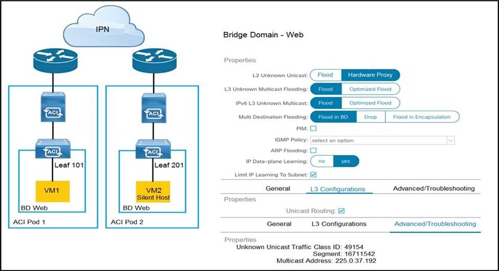
How is the ARP request from VM1 forwarded when VM2 is not learned in the Cisco ACI fabric?
- A . Leaf 101 forwards the ARP request to one of the proxy VTEP spines.
- B . POD1 spine responds to the ARP request after the POD1 COOP is updated with the VM2 location.
- C . Leaf 101 encapsulates the ARP request into a multicast packet that is destined to 225.0.37.192.
- D . Leaf 101 switch consumes the ARP reply of VM2 to update the local endpoint table.
A
Explanation:
In a Cisco ACI environment, when an ARP request is initiated by VM1 for VM2 and VM2 is not known within the ACI fabric, the leaf switch (Leaf 101) will forward the ARP request to a spine switch that acts as a proxy VTEP. The spine switch will either respond to the ARP request if it knows VM2’s location through the COOP database or will flood the ARP request within the fabric if VM2’s location is unknown.
Reference: Implementing Cisco Application Centric Infrastructure Official Cert Guide
What is the outer destination IP address in the VXLAN encapsulated packet for Layer 2 Broadcast. Unknown-unicast and Multicast (BUM) that is sent between two Cisco AC I sites?
- A . Overlay Unicast TEP
- B . MP-BGPEVPN Router-ID
- C . Multi-Pod Data-Plane TEP
- D . Overlay Multicast TEP
D
Explanation:
The outer destination IP address in the VXLAN encapsulated packet for Layer 2 Broadcast, Unknown-unicast, and Multicast (BUM) traffic sent between two Cisco ACI sites is the Overlay Multicast TEP (Tunnel Endpoint). This address ensures efficient replication of BUM traffic across different sites in the ACI fabric.
Reference: = Cisco APIC Layer 2 Networking Configuration Guide
Refer to the exhibit.
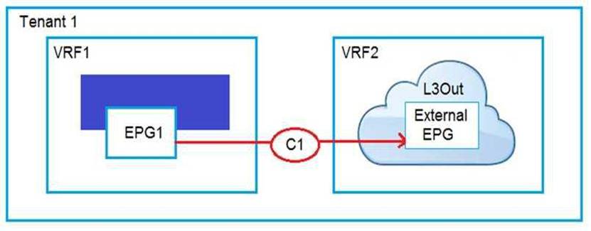
An engineer must have communication between EPG1 in VRF1 and External EPG in VRF2.
Which three actions should be taken for the defined subnets in the L3Out External EPG to accomplish this goal? (Choose three.)
- A . Enable Shared Route Control Subnet
- B . Enable External Subnets for External EPG
- C . Enable Export Route Control Subnet
- D . Enable Shared Security Import Subnet
- E . Enable Aggregate Shared Routes
- F . Enable Import Route Control Subnet
A, B, F
Explanation:
To facilitate communication between EPG1 in VRF1 and External EPG in VRF2, the following actions are necessary:
Enable Shared Route Control Subnet: This allows subnets to be shared across different VRFs, which is essential for inter-VRF communication.
Enable External Subnets for External EPG: Activating this makes the subnets within the External EPG routable to external networks.
Enable Import Route Control Subnet: This enables the importation of routes from L3Out into the VRF, permitting connectivity between different VRFs.
These steps ensure that routing and security policies are correctly implemented to permit traffic flow between EPG1 and External EPG across distinct VRFs.
Reference: Implementing Cisco Application Centric Infrastructure Official Cert Guide
Refer to the exhibit.
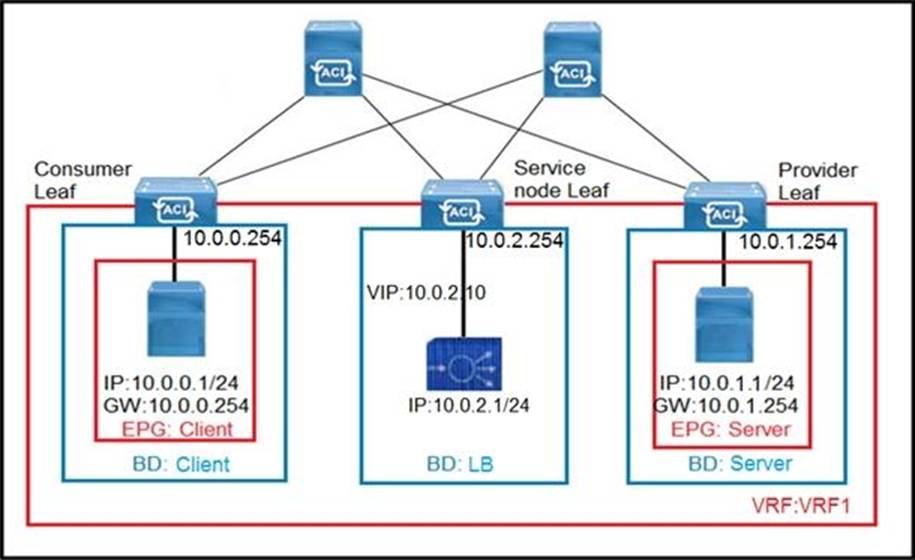
The client endpoint uses the load-balancer VIP as the destination address to send traffic to the server endpoint. If the load balancer does not do source NAT, which set of configurations must be applied on Cisco ACI to allow only the return traffic to be redirected to the service node?
- A . Create a contract with a filter matching “IP” only Create a L4-L7 device, function type “GoTo” Create a L4-L7 Policy-Based Redirect Policy with the L3 Destination set to the load-balancer inside IP/MAC
Create a service graph template that references the previously created contract and L4-L7 device Apply the service graph template. Select “L3 Destination” and reference L4-L7 Policy-Based Redirect Policy on the provider connector only - B . Create a contract linked to the common/default filter Create a L4-L7 device, function type “GoThrough”
Create a L4-L7 Policy-Based Redirect Policy with the L3 Destination set to the load-balancer inside IP/MAC
Create a service graph template that references the previously created contract and L4-L7 device Apply the service graph template. Select “L3 Destination” and reference L4-L7 Policy-Based Redirect Policy on the consumer and provider connector - C . Create a contract linked to the common/default filter Create a L4-L7 device, function type “GoTo”
Create a L4-L7 Policy-Based Redirect Policy with “Anycast Endpoint” enabled and the L3 Destination set to the load-balancer inside IP/MAC
Create a service graph template that references the previously created contract and L4-L7 device Apply the service graph template. Select “L3 Destination” and reference L4-L7 Policy-Based Redirect Policy on the consumer connector only - D . Create a contract with a filter matching “IP” only Create a L4-L7 device, function type “GoThrough”
Create a L4-L7 Policy-Based Redirect Policy with “Anycast Endpoint” enabled and the L3 Destination set to the load-balancer inside IP/MAC
Create a service graph template that references the previously created contract and L4-L7 device Apply the service graph template. Select “L3 Destination” and reference L4-L7 Policy-Based Redirect Policy on the consumer and provider
B
Explanation:
To allow only the return traffic to be redirected to the service node when the load balancer does not perform source NAT, we need to configure a Policy-Based Redirect (PBR).
Here’s how it can be achieved:
Create a Contract:
Create a contract linked to the common/default filter. This contract will define the communication rules between the client endpoint and the server endpoint.
Configure L4-L7 Device:
Create an L4-L7 device with the function type set to “GoThrough.” This device will be used to redirect traffic to the service node.
Create a Policy-Based Redirect Policy:
Set up a Policy-Based Redirect (PBR) policy.
Specify the L3 Destination as the load balancer’s inside IP/MAC address.
Ensure that the L4-L7 Policy-Based Redirect Policy has the “GoThrough” function type.
Create a Service Graph Template:
Define a service graph template that references the previously created contract and L4-L7 device. Apply the service graph template to the relevant connectors. Connector Configuration:
On the consumer connector, reference the L4-L7 Policy-Based Redirect Policy.
On the provider connector, also reference the L4-L7 Policy-Based Redirect Policy.
By following this configuration, only the return traffic (from the server to the client) will be redirected to the service node, ensuring proper load balancing and traffic management.
Reference: Implementing Cisco Application Centric Infrastructure Official Cert Guide
An engineer is configuring ACI Multi-Pod between two data centers and must plan the physical cabling in the primary data center.
How must the Cisco ACI Multi-Pod topology be connected?
- A . Connect spine switch 201 and 202 in pod 1 directly to spine switch 201 and 202 in pod 2.
- B . Connect leaf switch 101 and 102 in pod 1 directly to leaf switch 101 and 102 in pod 2
- C . Connect spine switch 201 and 202 in pod 1 to ports on a device that is providing IP connectivity between pods
- D . Connect leaf switch 101 and 102 in pod 1 to ports on a device that is providing IP connectivity between pods.
C
Explanation:
In a Cisco ACI Multi-Pod deployment, the spine switches within a pod should not be directly connected to the spine switches in another pod. Instead, they should be connected to an IPN (Inter-Pod Network) device that provides Layer 3 IP connectivity between the pods. This setup allows for the extension of the ACI fabric across multiple locations while maintaining a single logical fabric. The IPN device can be a router or a switch with Layer 3 capabilities that can handle the necessary routing protocols and encapsulation methods required for Multi-Pod communication.
Reference: = Implementing Cisco Application Centric Infrastructure Official Cert Guide
The engineer notices frequent MAC and IP address moves between different leaf switch ports.
Which action prevents this problem from occurring?
- A . Disable enforce subnet check.
- B . Disable IP bridge domain enforcement.
- C . Enable endpoint loop protection.
- D . Enable rogue endpoint control.
C
Explanation:
Enabling endpoint loop protection is the action that prevents frequent MAC and IP address moves between different leaf switch ports. This feature helps to identify and mitigate loops within the network, which can cause these frequent address moves. By detecting and blocking the looped interfaces, it stabilizes the network and stops the address flapping.
What is the advantage of implementing an active-active firewall cluster that is stretched across separate pods when anycast services are configured?
- A . A different MAC/IP combination can be configured for the firewall in each pod.
- B . The local pod anycast node is preferred by the local spines.
- C . A cluster can be deployed in transparent mode across pods.
- D . Local traffic in a pod is load-balanced between the clustered firewalls.
B
Explanation:
Implementing an active-active firewall cluster stretched across separate pods with anycast services configured offers several advantages, one of which is that it allows for optimized routing within the Cisco ACI fabric. When anycast services are used, each pod can have its own anycast node (firewall instance), and due to routing preferences set within ACI’s spine switches, they will prefer their local pod’s anycast node for routing decisions. This preference enhances efficiency by reducing cross-pod traffic and improving response times since local spines direct traffic to their respective local pod’s anycast nodes.
Reference: Implementing Cisco Application Centric Infrastructure Official Cert Guide
An engineer is deploying a Cisco ACI fabric and discovers that the traffic to certain endpoints is dropped. The originating bridge domain is configured with hardware proxy.
Which action prevents this problem?
- A . Set the L2 Unknown Unicast option to Flood for Layer 2 switched traffic.
- B . Set the L2 Unknown Unicast option to Hardware-Proxy for Layer 2 switched traffic.
- C . Enable the ARP Flooding option under the bridge domain for Layer 3 routed traffic.
- D . Disable the ARP Flooding option under the bridge domain for Layer 3 routed traffic.
A
Explanation:
When traffic to certain endpoints is dropped in a Cisco ACI fabric configured with hardware proxy, setting the L2 Unknown Unicast option to Flood for Layer 2 switched traffic can prevent this problem. This mode allows unknown unicast traffic to be flooded within the bridge domain, rather than being sent to the spine proxy and potentially discarded if the destination is unknown5.
Reference: = Solved: Unknown Unicast in ACI Fabric – Cisco Community
What is the purpose of enabling ARP flooding when VMs are migrated from a pre-existing network to Cisco ACI and their gateways remain configured in the legacy setup?
- A . to avoid endpoint flapping between the legacy network and the ACI fabric
- B . to prevent VMs from communicating with physical servers within the ACI fabric
- C . to allow communication between VMs and silent hosts
- D . to allow VMs to communicate with devices outside of their subnet
C
Explanation:
Enabling ARP flooding is necessary when VMs are migrated from a pre-existing network to Cisco ACI and their gateways remain in the legacy setup. This allows the ACI fabric to learn about silent hosts that do not initiate communication, ensuring that the migrated VMs can communicate with all hosts in the network, including those that are silent.
Refer to the exhibit.
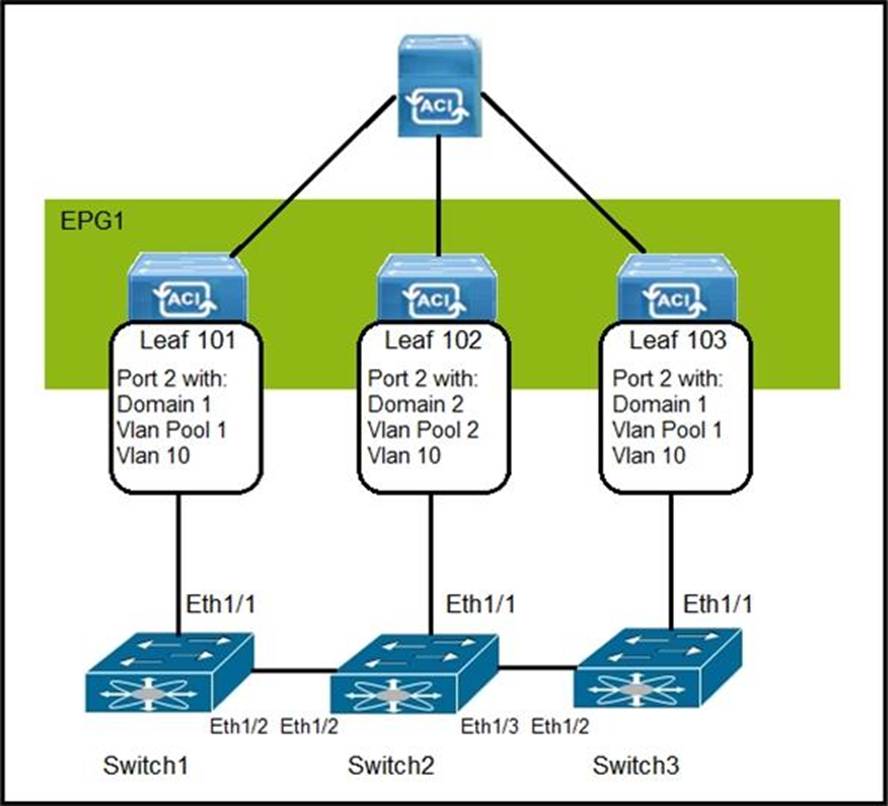
How are the STP BPDUs forwarded over Cisco ACI fabric?
- A . STP BPDUs that are generated by Switch2 are received by Switch1 and Switch3.
- B . Cisco ACI fabric drops all STP BPDUs that are generated by the external switches.
- C . Cisco ACI acts as the STP root for all three external switches.
- D . STP BPDUs that are generated by Switch1 are received only by Switch3.
B
Explanation:
In a Cisco ACI environment, STP BPDUs are not forwarded across the fabric. The ACI fabric is designed
to operate without STP, using a policy-driven, multi-path Ethernet model for loop prevention. Thus, STP BPDUs from external switches are dropped by the ACI leaf switches.
Reference: = (Implementing Cisco Application Centric Infrastructure Official Cert Guide)