
Cisco 300-410 Practice Exams
Last updated on Nov 16,2026- Exam Code: 300-410
- Exam Name: Implementing Cisco Enterprise Advanced Routing and Services (ENARSI)
- Certification Provider: Cisco
- Latest update: Nov 16,2026
DRAG DROP
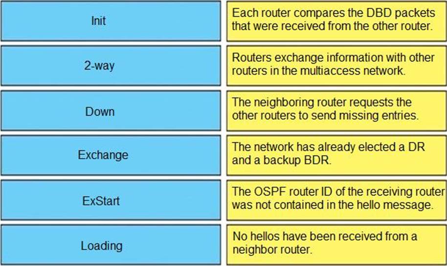
Drag and drop the OSPF adjacency states from the left onto the correct descriptions on the right.
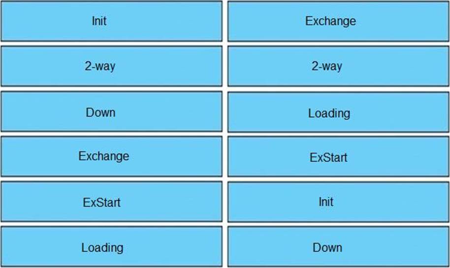
Explanation:
Table Description
automatically generated
(Reference: http://www.cisco.com/en/US/tech/tk365/technologies_tech_note09186a0080093f0e.sh tml)
Reference: https://www.cisco.com/c/en/us/support/docs/ip/open-shortest-path-first-ospf/13685-13.html
Down
This is the first OSPF neighbor state. It means that no information (hellos) has been received from this neighbor, but hello packets can still be sent to the neighbor in this state.
During the fully adjacent neighbor state, if a router doesn’t receive hello packet from a neighbor within the Router Dead Interval time (RouterDeadInterval = 4*HelloInterval by default) or if the
manually configured neighbor is being removed from the configuration, then the neighbor state changes from Full to Down.
Attempt
This state is only valid for manually configured neighbors in an NBMA environment. In Attempt state, the router sends unicast hello packets every poll interval to the neighbor, from which hellos have not been received within the dead interval.
Init
This state specifies that the router has received a hello packet from its neighbor, but the receiving router’s ID was not included in the hello packet. When a router receives a hello packet from a neighbor, it should list the sender’s router ID in its hello packet as an acknowledgment that it received a valid hello packet.
2-Way
This state designates that bi-directional communication has been established between two routers. Bi-directional means that each router has seen the other’s hello packet. This state is attained when the router receiving the hello packet sees its own Router ID within the received hello packet’s neighbor field. At this state, a router decides whether to become adjacent with this neighbor. On broadcast media and non-broadcast multiaccess networks, a router becomes full only with the designated router (DR) and the backup designated router (BDR); it stays in the 2-way state with all other neighbors. On Point-to-point and Point-to-multipoint networks, a router becomes full with all connected routers.
At the end of this stage, the DR and BDR for broadcast and non-broadcast multiaccess networks are elected. For more information on the DR election process, refer to DR Election.
Note: Receiving a Database Descriptor (DBD) packet from a neighbor in the init state will also a cause
a transition to 2-way state. Exstart
Once the DR and BDR are elected, the actual process of exchanging link state information can start between the routers and their DR and BDR. (ie. Shared or NBMA networks).
In this state, the routers and their DR and BDR establish a master-slave relationship and choose the initial sequence number for adjacency formation. The router with the higher router ID becomes the master and starts the exchange, and as such, is the only router that can increment the sequence number. Note that one would logically conclude that the DR/BDR with the highest router ID will become the master during this process of master-slave relation. Remember that the DR/BDR election might be purely by virtue of a higher priority configured on the router instead of highest router ID. Thus, it is possible that a DR plays the role of slave. And also note that master/slave election is on a per-neighbor basis.
Exchange
In the exchange state, OSPF routers exchange database descriptor (DBD) packets. Database descriptors contain link-state advertisement (LSA) headers only and describe the contents of the entire link-state database. Each DBD packet has a sequence number which can be incremented only by master which is explicitly acknowledged by slave. Routers also send link-state request packets and link-state update packets (which contain the entire LSA) in this state. The contents of the DBD received are compared to the information contained in the routers link-state database to check if new or more current link-state information is available with the neighbor.
Loading
In this state, the actual exchange of link state information occurs. Based on the information provided by the DBDs, routers send link-state request packets. The neighbor then provides the requested link-state information in link-state update packets. During the adjacency, if a router receives an outdated or missing LSA, it requests that LSA by sending a link-state request packet. All link-state update packets are acknowledged.
Full
In this state, routers are fully adjacent with each other. All the router and network LSAs are exchanged and the routers’ databases are fully synchronized.
Full is the normal state for an OSPF router. If a router is stuck in another state, it is an indication that there are problems in forming adjacencies. The only exception to this is the 2-way state, which is normal in a broadcast network. Routers achieve the FULL state with their DR and BDR in NBMA/broadcast media and FULL state with every neighbor in the remaining media such as point-to-point and point-to-multipoint.
Note: The DR and BDR that achieve FULL state with every router on the segment will display FULL/DROTHER when you enter the show ip ospf neighbor command on either a DR or BDR. This simply means that the neighbor is not a DR or BDR, but since the router on which the command was entered is either a DR or BDR, this shows the neighbor as FULL/DROTHER.
Reference: https://www.cisco.com/c/en/us/support/docs/ip/open-shortest-path-first-ospf/13685-13.html
Reference: http://www.cisco.com/en/US/tech/tk365/technologies_tech_note09186a0080093f0e.sht ml)
Reference: https://www.cisco.com/c/en/us/support/docs/ip/open-shortest-path-first-ospf/13685-13.html
How does an MPLS Layer 3 VPN function?
- A . set of sites use multiprotocol BGP at the customer site for aggregation
- B . multiple customer sites interconnect through service provider network to create secure tunnels between customer edge devices
- C . set of sites interconnect privately over the Internet for security
- D . multiple customer sites interconnect through a service provider network using customer edge to provider edge connectivity
D
Explanation:
A Multiprotocol Label Switching (MPLS) Layer 3 Virtual Private Network (VPN) consists of a set of sites that are interconnected by means of an MPLS provider core network. At each customer site, one or more customer edge (CE) routers attach to one or more provider edge (PE) routers.
Reference: https://www.cisco.com/c/en/us/td/docs/routers/asr9000/software/asr9k-r6-5/lxvpn/configuration/guide/b-l3vpn-cg-asr9000-65x/b-l3vpn-cg-asr9000-65x_chapter_010.pdf
How does an MPLS Layer 3 VPN function?
- A . set of sites use multiprotocol BGP at the customer site for aggregation
- B . multiple customer sites interconnect through service provider network to create secure tunnels between customer edge devices
- C . set of sites interconnect privately over the Internet for security
- D . multiple customer sites interconnect through a service provider network using customer edge to provider edge connectivity
D
Explanation:
A Multiprotocol Label Switching (MPLS) Layer 3 Virtual Private Network (VPN) consists of a set of sites that are interconnected by means of an MPLS provider core network. At each customer site, one or more customer edge (CE) routers attach to one or more provider edge (PE) routers.
Reference: https://www.cisco.com/c/en/us/td/docs/routers/asr9000/software/asr9k-r6-5/lxvpn/configuration/guide/b-l3vpn-cg-asr9000-65x/b-l3vpn-cg-asr9000-65x_chapter_010.pdf
Refer to the exhibit.

When monitoring an IPv6 access list, an engineer notices that the ACL does not have any hits and is causing unnecessary traffic to pass through the interface.
Which command must be configured to resolve the issue?
- A . access-class INTERNET in
- B . ipv6 traffic-filter INTERNET in
- C . ipv6 access-class INTERNET in
- D . ip access-group INTERNET in
How is a preshared key "Test’’ for all the remote VPN rooters configured In a DMVPN using GRE over IPsec set up?
- A . authentication pre-share Test address 0.0.0.0 0.0.0.0
- B . set pre-share Test address 0.0.0.0 0.0.0.0
- C . crypto Ipsec key Test address 0.0.0.0 0.0.0.0
- D . crypto isakmp key Test address 0.0.0.0 0.0.0.0
Refer to the exhibit.
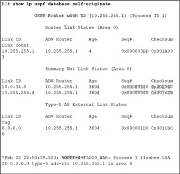
After configuring OSPF in R1, some external destinations in the network became unreachable.
Which action resolves the issue?
- A . Clear the OSPF process on R1 to flush stale LSAs sent by other routers.
- B . Change the R1 router ID from 10.255.255.1 to a unique value and clear the process.
- C . Increase the SPF delay interval on R1 to synchronize routes.
- D . Disconnect the router with the OSPF router ID 0.0.0.0 from the network.
Refer to the exhibit.
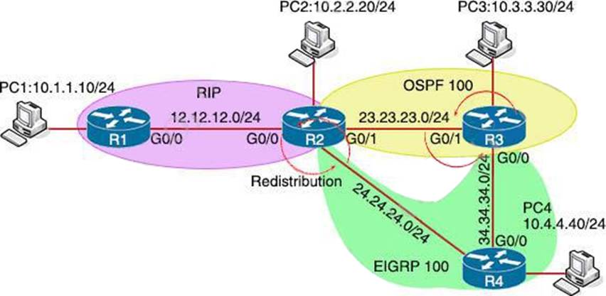
After redistribution is enabled between the routing protocols; PC2, PC3, and PC4 cannot reach PC1.
Which action can the engineer take to solve the issue so that all the PCs are reachable?
- A . Set the administrative distance 100 under the RIP process on R2.
- B . Filter the prefix 10.1.1.0/24 when redistributed from OSPF to EIGRP.
- C . Filter the prefix 10.1.1.0/24 when redistributed from RIP to EIGRP.
- D . Redistribute the directly connected interfaces on R2.
Which method provides failure detection in BFD?
- A . short duration, high overhead
- B . short duration, low overhead
- C . long duration, high overhead
- D . long duration, low overhead
Refer to the exhibit.
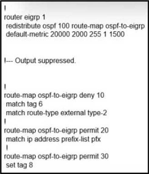
Which action fixes the OSPF routes redistribution into EIGRP?
- A . Match external type to type-1
- B . Set tags before matching into EIGRP
- C . Set a default metric in the route map
- D . Match OSPF and EIGR IDs
An engineer is implementing a coordinated change with a server team. As part of the change, the engineer must configure interlace GigabitEthernet2 in an existing VRF "RED" then move the interface to an existing VRF "BLUE" when the server team is ready.
The engineer configured interface GigabitEthemet2 in VRF "RED"
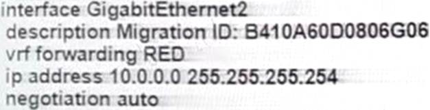
Which configuration completes the change?
- A . interface GigabitEthernet2
no ip address
vrf forwarding BLUE - B . interface GigabitEthernet2
no vrf forwarding RED
vrf forwarding BLUE
ip address 10.0.0.0 255.255.255.254 - C . interface GigabitEthernet2
no vrf forwarding RED
vrf forwarding BLUE - D . interface GigabitEthernet2
no ip address
ip address 10.0.0.0 255.255.255.254
vrf forwarding BLUE
B
Explanation:
When assigning an interface to a VRF, the IP address will be removed so we have to reassign the IP address to that interface.