
DELL EMC D-PVM-OE-01 Practice Exams
Last updated on Nov 16,2026- Exam Code: D-PVM-OE-01
- Exam Name: Dell PowerMax Operate v2 Exam
- Certification Provider: DELL EMC
- Latest update: Nov 16,2026
Which three device types can be managed using Solutions Enabler and Unisphere?
- A . SRDF Thin Devices (RDF1 or RDF2)
- B . Thin BCV Devices (BCV+TDEV)
- C . Internal Thin Devices (Int+TDEV)
- D . Data Devices (TDATs)
- E . Thin Devices (TDEV)
ACE
Explanation:
Step by Step Comprehensive Detailed
Dell PowerMax storage arrays utilize different device types for various purposes. Solutions Enabler (SYMCLI) and Unisphere for PowerMax are management tools that can interact with these device types. Here’s a breakdown:
SRDF Thin Devices (RDF1 or RDF2): These devices are specifically used for SRDF (Symmetrix Remote Data Facility) replication. RDF1 devices represent the local copy of data in an SRDF relationship, while RDF2 devices represent the remote copy. Both Solutions Enabler and Unisphere can manage these devices to configure and monitor SRDF replication.
Internal Thin Devices (Int+TDEV): These are thin provisioned devices that reside within the PowerMax storage array. They are used for general storage purposes and can be managed by both Solutions Enabler and Unisphere for tasks like provisioning, allocating capacity, and monitoring performance.
Thin Devices (TDEV): This is a general term for thin provisioned devices in PowerMax. Thin provisioning allows for efficient storage utilization by allocating capacity on demand. 1 Both Solutions Enabler and Unisphere can manage these devices.
https://www.n-able.com/blog/thin-provision-vs-thick-provision#:~:text=Thin%20provisioning%20allocates%20disk%20space,need%20at%20any%20given %20time.
https://www.n-able.com/blog/thin-provision-vs-thick-provision#:~:text=Thin%20provisioning%20allocates%20disk%20space,need%20at%20any%20given %20time.
Why other options are incorrect:
B. Thin BCV Devices (BCV+TDEV): BCV (Business Continuance Volume) devices are used for creating point-in-time copies for disaster recovery. While Solutions Enabler can manage BCV devices, Unisphere for PowerMax has limited functionality for managing them directly.
D. Data Devices (TDATs): TDATs are physical devices within the PowerMax array. While Solutions Enabler can interact with TDATs at a lower level, Unisphere for PowerMax primarily focuses on managing logical devices and storage groups.
Reference and documents of Dell’s public documentation for PowerMax Operate v.2:
Dell PowerMax Family: Essentials and Best Practices Guide: This guide provides an overview of PowerMax devices and their management. It mentions the different device types and how they are used in the PowerMax environment.
Dell Solutions Enabler 10.0.0 CLI User Guide: This guide provides detailed information about Solutions Enabler commands for managing various device types, including SRDF devices, thin devices, and internal devices.
Dell Unisphere for PowerMax 10.0.0 Online Help: The online help documentation for Unisphere for PowerMax explains how to manage different device types through the graphical user interface, including provisioning, monitoring, and configuring storage.
An administrator is using the Workload Planner feature in Unisphere for PowerMax.
How does the Planner calculate if the Storage Group workload is stable?
- A . One of the calculated values is within 10-20% of the SL-defined response time
- B . Both calculated values are within a 10-15% threshold of the SL-defined response time
- C . One of the calculated values remains within the SL-defined response time
- D . Both calculated values are within the SL-defined response time.
D
Explanation:
Step by Step Comprehensive Detailed
The Workload Planner in Unisphere for PowerMax helps you analyze and predict the performance impact of adding new workloads to your storage array. It uses sophisticated algorithms to calculate how the addition of a new workload will affect the existing workloads and whether it will violate any service level objectives (SLOs).
To determine if a Storage Group workload is stable, the Planner considers two key calculated values:
Read Response Time: The predicted read response time of the Storage Group after the new workload is added.
Write Response Time: The predicted write response time of the Storage Group after the new workload is added.
The Planner compares these calculated values against the service level (SL) defined for the Storage Group. If both the calculated read and write response times fall within the defined SL response time, the Planner considers the workload to be stable. This means that the new workload can be added without negatively impacting the performance of the existing workloads or violating the SLOs.
Why other options are incorrect:
On a PowerMax array, what is the default Dynamic I/O distribution mode setting when a Storage Group is associated with Host I/O Limits’?
- A . OnFailure
- B . Balanced
- C . Never
- D . Always
C
Explanation:
Host I/O Limits in PowerMax allow you to control the maximum IOPS (Input/Output Operations Per Second) or bandwidth that a storage group can consume. This helps prevent performance issues caused by one application or workload monopolizing resources.
When you associate Host I/O Limits with a Storage Group, the default Dynamic I/O distribution mode is set to Never.
Never: This means that the I/O limits are statically distributed across the directors in the associated masking view. If a director fails, its allocated portion of the I/O limit is lost. This is the most conservative setting, as it ensures that the I/O limits are strictly enforced even in the event of a director failure.
You can change this setting to Balanced or Always if you need more dynamic distribution of I/O limits.
Reference and documents of Dell’s public documentation for PowerMax Operate v.2:
Dell PowerMax and VMware vSphere Configuration Guide: This guide provides detailed information about Host I/O Limits, including the different distribution modes and their benefits. You can find this document on the Dell Support website by searching for "PowerMax and VMware vSphere Configuration Guide."
Dell Solutions Enabler 10.0.0 CLI User Guide: This guide provides information on how to set Host I/O Limits using SYMCLI commands, including the -dynamic option for specifying the distribution mode.
DRAG DROP
Place the steps to create a snapshot in Unisphere for PowerMax in the correct order
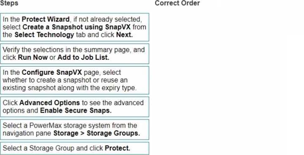
Explanation:
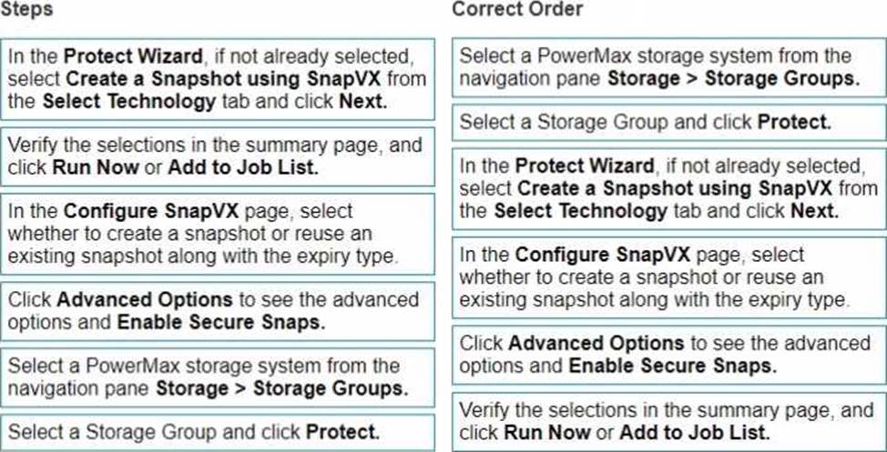
Okay, I’m ready to arrange those steps for creating a snapshot in Unisphere for PowerMax in the correct order, based on the image provided.
Here is the correct sequence, along with explanations:
Correct Order:
Select a PowerMax storage system from the navigation pane Storage > Storage Groups.
Why: This is the starting point in Unisphere. You need to navigate to the "Storage Groups" section within the specific PowerMax array where you intend to create the snapshot.
Select a Storage Group and click Protect.
Why: You’re choosing the storage group that contains the data you want to snapshot. Clicking "Protect" initiates the process of creating a data protection operation (in this case, a snapshot).
In the Protect Wizard, if not already selected, select Create a Snapshot using SnapVX from the Select Technology tab and click Next.
Why: This specifies that you want to use the SnapVX technology to create a snapshot. SnapVX is the snapshot feature in PowerMax arrays.
In the Configure SnapVX page, select whether to create a snapshot or reuse an existing snapshot along with the expiry type.
Why: Here, you define the core parameters of the snapshot:
Create a new snapshot: This is what you’d typically do for a new point-in-time copy.
Reuse an existing snapshot: In some cases, you might want to update an existing snapshot.
Expiry type: This determines how long the snapshot will be retained (e.g., a specific duration or until manually deleted).
Click Advanced Options to see the advanced options and Enable Secure Snaps.
Why: This allows you to configure more granular settings for the snapshot, including:
Secure Snaps: Enabling this option prevents the snapshot from being deleted before its expiry time, adding an extra layer of protection.
Verify the selections in the summary page, and click Run Now or Add to Job List.
Why: This is the final step before creating the snapshot:
Summary page: Review all the settings you’ve configured.
Run Now: Immediately creates the snapshot.
Add to Job List: Schedules the snapshot creation for later.
Select a PowerMax storage system from the navigation pane Storage > Storage Groups.
Select a Storage Group and click Protect.
In the Protect Wizard, if not already selected, select Create a Snapshot using SnapVX from the Select Technology tab and click Next.
In the Configure SnapVX page, select whether to create a snapshot or reuse an existing snapshot
along with the expiry type.
Click Advanced Options to see the advanced options and Enable Secure Snaps.
Verify the selections in the summary page, and click Run Now or Add to Job List.
DRAG DROP
Place the steps to create a snapshot in Unisphere for PowerMax in the correct order
Explanation:
Okay, I’m ready to arrange those steps for creating a snapshot in Unisphere for PowerMax in the correct order, based on the image provided.
Here is the correct sequence, along with explanations:
Correct Order:
Select a PowerMax storage system from the navigation pane Storage > Storage Groups.
Why: This is the starting point in Unisphere. You need to navigate to the "Storage Groups" section within the specific PowerMax array where you intend to create the snapshot.
Select a Storage Group and click Protect.
Why: You’re choosing the storage group that contains the data you want to snapshot. Clicking "Protect" initiates the process of creating a data protection operation (in this case, a snapshot).
In the Protect Wizard, if not already selected, select Create a Snapshot using SnapVX from the Select Technology tab and click Next.
Why: This specifies that you want to use the SnapVX technology to create a snapshot. SnapVX is the snapshot feature in PowerMax arrays.
In the Configure SnapVX page, select whether to create a snapshot or reuse an existing snapshot along with the expiry type.
Why: Here, you define the core parameters of the snapshot:
Create a new snapshot: This is what you’d typically do for a new point-in-time copy.
Reuse an existing snapshot: In some cases, you might want to update an existing snapshot.
Expiry type: This determines how long the snapshot will be retained (e.g., a specific duration or until manually deleted).
Click Advanced Options to see the advanced options and Enable Secure Snaps.
Why: This allows you to configure more granular settings for the snapshot, including:
Secure Snaps: Enabling this option prevents the snapshot from being deleted before its expiry time, adding an extra layer of protection.
Verify the selections in the summary page, and click Run Now or Add to Job List.
Why: This is the final step before creating the snapshot:
Summary page: Review all the settings you’ve configured.
Run Now: Immediately creates the snapshot.
Add to Job List: Schedules the snapshot creation for later.
Select a PowerMax storage system from the navigation pane Storage > Storage Groups.
Select a Storage Group and click Protect.
In the Protect Wizard, if not already selected, select Create a Snapshot using SnapVX from the Select Technology tab and click Next.
In the Configure SnapVX page, select whether to create a snapshot or reuse an existing snapshot
along with the expiry type.
Click Advanced Options to see the advanced options and Enable Secure Snaps.
Verify the selections in the summary page, and click Run Now or Add to Job List.
A storage administrator is using SE 10 to query a PowerMax 2000 using symcfg list -dir and wants to seethe number of Cores that are assigned to the front-end emulations
What does the storage administrator need to do?
- A . Use the-mode v9x argument for backwards compatibility as some output has been deprecated
- B . Look for CPU instead of Cores as these have been rebranded to allow differentiating between virtual and physical hardware.
- C . Specify the full 12-digit serial number with -sidsoSE 10 understands the output relates to an older system model.
- D . Use syraconf igure -version -dir as in SE 10 support for outputs specific to older systems moved to a different command.
A
Explanation:
Step by Step Comprehensive Detailed
Solutions Enabler (SE) 10 introduces some changes to the output format of certain commands for better clarity and consistency. When querying a PowerMax 2000 (which is based on older VMAX architecture) using symcfg list -dir, you might encounter differences in the output compared to previous SE versions.
To ensure backward compatibility and see the output in the familiar format, you need to use the – mode v9x argument. This tells SE 10 to display the output in the style of SE 9.x, which is compatible
with the PowerMax 2000.
Why other options are incorrect:
B. Look for CPU instead of Cores as these have been rebranded…: While there might be terminology changes, this is not the primary reason for the output difference.
C. Specify the full 12-digit serial number with -sid so SE 10 understands…: The serial number is not directly related to the output format.
D. Use syraconfigure -version -dir as in SE 10 support for outputs…: The syraconfigure command is not the correct command for this purpose.
Reference and documents of Dell’s public documentation for PowerMax Operate v.2:
Dell Solutions Enabler 10.0.0 CLI User Guide: This guide provides detailed information about the symcfg command and its options, including the -mode argument for backward compatibility. You can find this document on the Dell Support website by searching for "Solutions Enabler CLI User Guide."
A storage administrator is using SE 10 to query a PowerMax 2000 using symcfg list -dir and wants to seethe number of Cores that are assigned to the front-end emulations
What does the storage administrator need to do?
- A . Use the-mode v9x argument for backwards compatibility as some output has been deprecated
- B . Look for CPU instead of Cores as these have been rebranded to allow differentiating between virtual and physical hardware.
- C . Specify the full 12-digit serial number with -sidsoSE 10 understands the output relates to an older system model.
- D . Use syraconf igure -version -dir as in SE 10 support for outputs specific to older systems moved to a different command.
A
Explanation:
Step by Step Comprehensive Detailed
Solutions Enabler (SE) 10 introduces some changes to the output format of certain commands for better clarity and consistency. When querying a PowerMax 2000 (which is based on older VMAX architecture) using symcfg list -dir, you might encounter differences in the output compared to previous SE versions.
To ensure backward compatibility and see the output in the familiar format, you need to use the – mode v9x argument. This tells SE 10 to display the output in the style of SE 9.x, which is compatible
with the PowerMax 2000.
Why other options are incorrect:
B. Look for CPU instead of Cores as these have been rebranded…: While there might be terminology changes, this is not the primary reason for the output difference.
C. Specify the full 12-digit serial number with -sid so SE 10 understands…: The serial number is not directly related to the output format.
D. Use syraconfigure -version -dir as in SE 10 support for outputs…: The syraconfigure command is not the correct command for this purpose.
Reference and documents of Dell’s public documentation for PowerMax Operate v.2:
Dell Solutions Enabler 10.0.0 CLI User Guide: This guide provides detailed information about the symcfg command and its options, including the -mode argument for backward compatibility. You can find this document on the Dell Support website by searching for "Solutions Enabler CLI User Guide."
DRAG DROP
Place the steps in the correct order to create clone copy sessions of device groups.
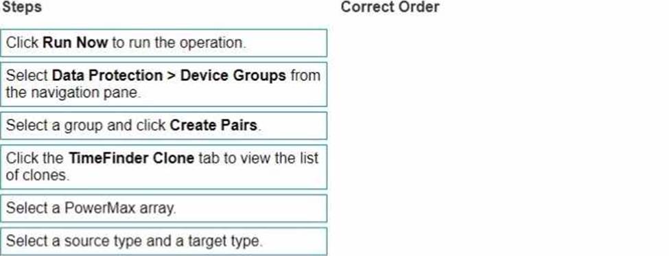
Explanation:
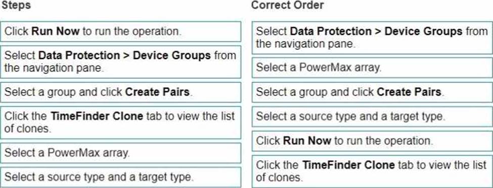
Here’s the correct sequence of steps along with explanations:
Correct Order:
Select Data Protection > Device Groups from the navigation pane.
Why: This is the starting point within Unisphere for PowerMax. You need to navigate to the section where device groups are managed and where TimeFinder operations are initiated.
Select a PowerMax array.
Why: In an environment with multiple PowerMax arrays, you must specify the array on which you want to create the clone copy sessions.
Select a group and click Create Pairs.
Why: You are selecting the specific device group that will be the source for the clone operation and choosing the "Create Pairs" action to initiate the clone session creation process. This implies you are creating a clone from an existing group of devices.
Select a source type and a target type.
Why: This step defines the characteristics of the source and target devices for the clone session. This could involve selecting from different storage groups, specifying thin or thick provisioning, or other relevant settings. Note that in a clone context, the "target type" often refers to how the clone will be linked to the source (e.g., a full copy or a linked target).
Click Run Now to run the operation.
Why: After configuring all the settings for the clone session, this action triggers the actual creation of the clone pairs based on the selected source and target types and other parameters.
Click the TimeFinder Clone tab to view the list of clones.
Why: Once the operation has been initiated, this is how you would verify that the clone sessions were created successfully and monitor their status.
Select Data Protection > Device Groups from the navigation pane.
Select a PowerMax array.
Select a group and click Create Pairs.
Select a source type and a target type.
Click Run Now to run the operation.
Click the TimeFinder Clone tab to view the list of clones.
Refer to the exhibit.
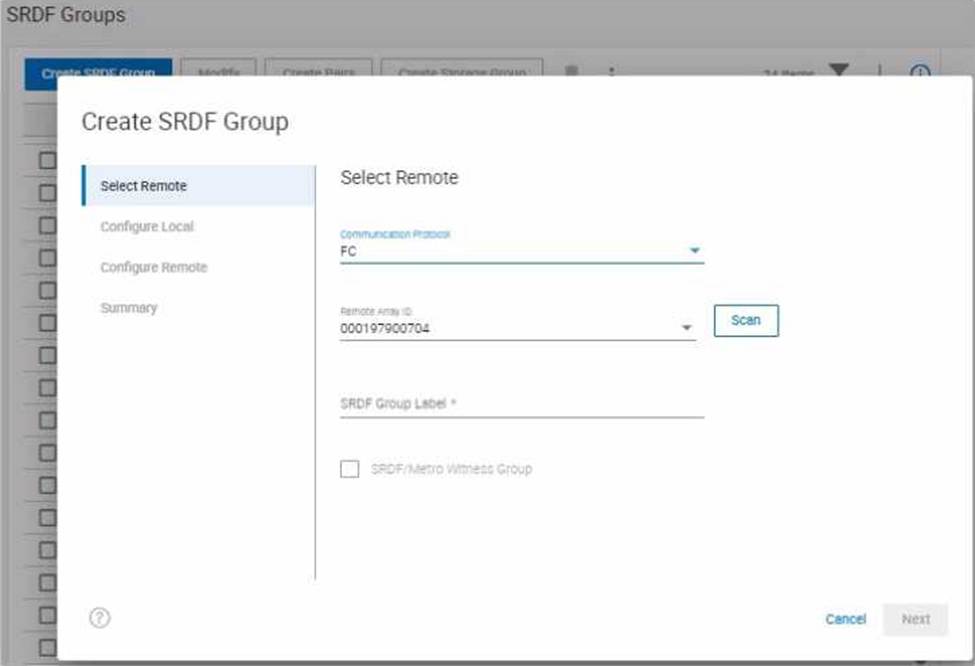
SRDF/Metro has been configured between two arrays using a physical witness.
When creating a new SRDF group for the configuration, why is the option to create an SRDF/Metro Witness Group greyed out?
- A . There can only be one SRDF/Metro Witness Group between two arrays
- B . SRDF/Metro Witness Groups can only be created with CLI.
- C . The SRDF Group Label needs to be left blank when creating an SRDF/Metro Witness Group
A
Explanation:
Step by Step Comprehensive Detailed
SRDF/Metro is a high-availability solution that provides synchronous replication between two storage arrays located within a metropolitan distance. It utilizes a witness to prevent data loss in the event of a split-brain scenario (where communication between the arrays is lost).
In SRDF/Metro, there can be only one Witness Group defined between two specific arrays. This Witness Group manages the witness device that acts as a tie-breaker in case of a communication failure between the arrays.
Since the exhibit shows that SRDF/Metro has already been configured between the two arrays using a physical witness, the option to create another SRDF/Metro Witness Group is grayed out because a Witness Group already exists for that pair of arrays.
Why other options are incorrect:
B. SRDF/Metro Witness Groups can only be created with CLI: While CLI can be used, Witness Groups can also be created through Unisphere for PowerMax.
C. The SRDF Group Label needs to be left blank when creating an SRDF/Metro Witness Group: This is not a requirement. Witness Groups can have labels.
Reference and documents of Dell’s public documentation for PowerMax Operate v.2:
Dell Solutions Enabler 10.0.0 SRDF Family CLI User Guide: This guide provides detailed information about SRDF/Metro configuration, including the role of the witness and the Witness Group. You can find this document on the Dell Support website by searching for "Solutions Enabler SRDF Family CLI User Guide."
Dell PowerMax Family: Essentials and Best Practices Guide: This guide offers a comprehensive overview of SRDF/Metro and its functionalities, including witness configuration and best practices.
What input is required when registering an ESXi server in Unisphere for PowerMax?
- A . Unisphere credentials and hostname
- B . IP address and hostname
- C . IP address and ESXi server credentials
- D . ESXi server credentials and Unisphere credentials
C
Explanation:
Step by Step Comprehensive Detailed
To register an ESXi server in Unisphere for PowerMax, you need to provide the following information:
IP Address: The IP address of the ESXi server that you want to manage. This allows Unisphere to communicate with the ESXi host.
ESXi Server Credentials: The username and password of an account with sufficient privileges to access and manage the ESXi server. This ensures that Unisphere has the necessary permissions to perform storage-related operations on the ESXi host.
Why other options are incorrect: